Thursday, October 2, 2014

Modding a Lattice CPLD ispMACH 4256ZE breakout board for an external clock

4256ZE Breakout Board with CLK PCB Operating
Taking a quote from the Lattice website this board is probably the best way of getting started with a CPLD I know of with 5V tolerant I/Os:

"The ispMACH 4256ZE Breakout Board is a simple, low-cost board that provides convenient access to densely-spaced IOs. Each I/O on the device is connected to 100-mil header holes. By adding test probes, jumper wires, or pin headers to the board, you can easily evaluate function and performace of the IO cells of the ispMACH 4256ZE."

The only issue I have with this board is that unlike its more modern version, the MachXO2 Breakout Board (note that its IOs are only 3.3V tolerant), it has no site for an external clock crystal on the PCB. This means you are limited to the internal 5MHz oscillator. Or not if you are clever and have access to PCB design software and are willing to spend $1 with OSH Park community PCB service.
The Oscillator series chosen for this project was the Fox FXO-HC53 series, a SMT crystal measuring 5mm by 3.2mm. Since this chip doesn't support LVDS we are using a HCMOS output. The two speeds chosen were 80MHz and 200MHz.
Note the oscillator is specified to drive up to 15pF and a CLK input pin on the ispMACH 4256ZE is 6pF max. The traces on the board are going to contribute further capacitance but it should be within spec.

The board design is detailed below:
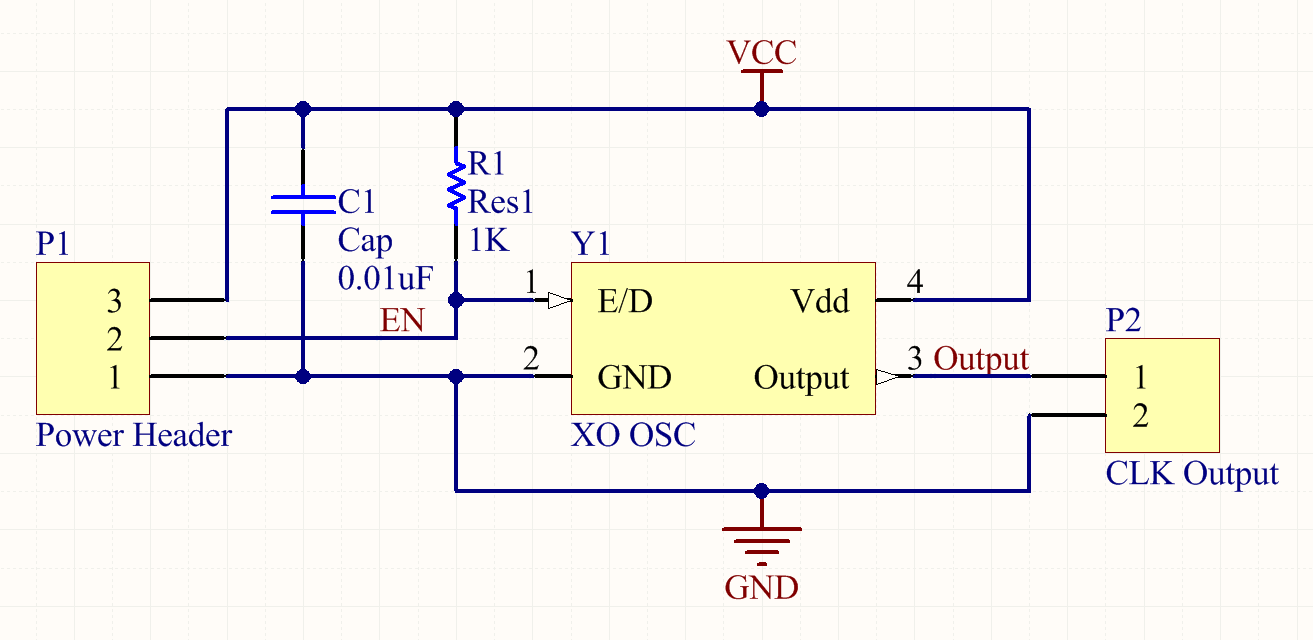
CLK Board Schematic

The PCB design has a few features that are worth noting:
  • The output pin of the oscillator is placed as close as possible to the output pin hole and the ground pin hole is as close as possible to the ground pin of the oscillator. This is to minimize impedance and coupling of the high frequency on the board.
  • There are two ground pins - one for the power supply and the other for the CLK return current to make it easier to interface.
  • A pullup resistor 0805 position is available in case the internal pullup proves insufficient or a different crystal is chosen.
  • The footprint of the crystal has the pad size extended outside the normal footprint by twice the length to allow manual soldering.
  • The power and output pins are in a row on a 0.1" spacing to allow compatibility with standard prototyping boards and systems.
  • The bottom of the board under the crystal and high frequency traces is one large ground plane.
  • Total board size is 525mil x 375mil.
CLK Board Top Layer


CLK Board Bottom Layer (Text not reversed)


OSH Park Rendering of the Manufactured PCB


Wednesday, September 17, 2014

Installing LaTeXML into a local directory...

I have been working for a while on a document management system that will use MathJax and .tex inputs to create pretty PDF output and good websites.

Researching the available converters the one that is most attractive and most maintained is LaTeXML.

Firstly I have to setup perl to install packages locally for me to use:

PATH="$PATH:~/perl5/bin"
export PERL5LIB=~/perl5/lib/perl5
export PERL_MB_OPT="--install_base '$HOME/perl5'"
export PERL_MM_OPT="INSTALL_BASE=$HOME/perl5"
curl -L http://cpanmin.us | perl - -l ~/perl5 App::cpanminus local::lib 

I now have to fetch and install LaTeXML:

cpanm http://search.cpan.org/CPAN/authors/id/B/BR/BRMILLER/LaTeXML-0.8.0.tar.gz --force
 
Note that you will need the prerequisite system libraries installed onto the system - this approach doesn't provide copies of LibXML etc. as needed.

Command lines:
latexml --dest=example.xml example.tex
latexmlpost --format=html5 --javascript='../MathJax_down/MathJax.js?config=TeX-AMS-MML_HTMLorMML' --destination=example.html example.xml
 
The results are really quite impressive - no links yet as they are behind our 'paywall' but hopefully soon.

A Blast From the Past: Valve/Tube/Electro-optic LA2A

Drip Electronics OPTO 6 version of the 1968 LA2A
When a friend of mine came and asked if I would help him build out an audio compressor that is based on tube amplification and some custom electro-optical cells I, of course, agreed!

The full details of the device are online at Drip Electronics: OPTO 6 (LA2A). They build a PCB to approximate the old point to point wiring typically found under tube systems as well as build the custom electro-optical cells.

Now I am not a tube guy nor an audio guy but any electronics that glows when it is working is good electronics.

Yours truly, (Matthew Swabey) testing the system with safety
 glasses in case one of the tubes or big caps "pops"
I really enjoyed the different construction style but testing was a real problem - the system is so non-linear, clips all the time and distorts it is almost impossible to know if I built it right. The current owner had to take it home and test with a microphone and speakers before it could be signed off.


Monday, July 14, 2014

Making ModelSim vsim and Questa vco work on Ubuntu 14.04

In my previous article, http://mattaw.blogspot.com/2014/05/making-modelsim-altera-starter-edition.html, I covered how to install and run the ModelSim-ALTERA starter edition on Ubuntu 14.04.

Subsequently it turns out this fix also applies to Mentor Graphic's ModelSim and Mentor Graphic's Questa (not that surprising as Questa is a superset of ModelSim with far greater capabilities).

The previous instructions for ModelSim ALTERA work for ModelSim.

Here are the detailed instructions to apply the fix to Questa:

Firstly complete installing everything including compiling the new libfreetype libraries and copying them into the questasim directory.

Now we need to edit the vco launch script to ensure the new freetype libraries are used:
sudo vim bin/vco
Search for the following line:
dir=`dirname $arg0`
and underneath add the following new line:
export LD_LIBRARY_PATH=${dir}/lib32
 
Test by running vco and hopefully you will be greeted by the Questa GUI.

Please email me any fixes or changes you would like so I can update this post and give credit.

Friday, June 20, 2014

Unlocking the temperature on a Weller WSL or WSD 81 Solder Station

[Credit for the fix goes to Todd Wild]

Just had a weird problem with my Weller WSL with WMP pencil:

Symptom of initial failure:
The base unit was resetting and making a clicking noise while the iron temperature dropped.

When I looked closer the clicking noise was a screw I had put on the top of the base unit - every time it reset the screw jumped!

After opening the WMP pencil I discovered the strain relief failed and the wires inside the iron were shorting. After fixing that it worked perfectly but the base unit had become locked to 375°C! [Speculation is that the EEPROM in the micro was corrupted by all the hard resets and/or the EM pulses].

Symptom of locked base unit:
Trying to change the temperature failed with the display just flashing when up or down is pushed. Just in case you didn't know nearly all solder stations for production environments can be locked to prevent inexperienced people altering the soldering parameters.

Solution:
Purchase a WCB1 calibrator for $1500 (only joking! read on...)

-or-
Opened WSL / WSD81 base unit - the reset jumper is to the right of the "up button" at the top right

  1. Open the case (spudgers needed, start with prying open the keyholes sideways on either side of the heatsink on the back and then pry the case up from the slots along both sides starting at the back. It should pop off towards the front).
  2. Install a jumper on the empty 0.1" pitch pins to the right of the "Up" button on the top right of the PCB. In the picture they are just visible to the right of the black square which is the up button.
  3. Power on the base unit - watch out for the live 120/240V!
  4. Wait for the display to show FSE.
  5. Remove the jumper while it is powered on.
  6. ...
  7. Profit!
Hope this may be of some use to someone else.

Thursday, June 19, 2014

Making my Lenovo MCE RC-6 IR Receiver immune to interference by my TV backlight - Success

Please see this article for the starting point of this work.

Installing the new Vishay module has completely solved my problem with the TV backlight. It was terribly simple as the part is 100% compatible with the original design.

Excellent!

Laird Tpcm 7250 is as good as Honeywell PTM7950 as thermal paste / interface for PC

[This is not very scientific, however it is notable. At 7.5W/m-K vs the installed SYY-157 at 15.7 W/m-K it performed better in real world lo...